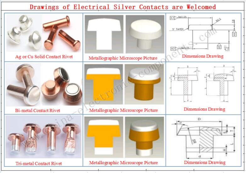
The Electric Silver Point Contact is key part of Relay and Low voltage electrical appliances.Under normal temperature and pressure, the breakdown voltage of the key dielectric in the air is 200-300V. Therefore, our goal is generally to control the voltage below 200V or less. Through the relay contact protection circuit, we generally have the following centralized methods to suppress:
1. Relay connected in series with RC circuit
This form is mainly suitable for circuits where the rated working voltage of the relay is lower than the power supply voltage. After the circuit is closed, the current of the relay coil increases due to the magnetic induction phenomenon, and the electromotive force interferes with the coil, thereby prolonging the inhalation time. After the RC circuit is connected in series, the inhalation time is shortened. The principle is that at the moment when the circuit is closed, the voltage across the capacitor c cannot be regarded as a sudden short circuit. This adds a supply voltage to the coil that is higher than the rated operating voltage of the relay coil, thereby increasing the rate at which the current in the coil increases, allowing the relay to absorb faster. After the power supply is stable, the capacitor c cannot work, and the resistor r acts as a current limiter.
2. The relay is connected in parallel with the RC circuit
When the circuit is closed, the RC circuit cannot work when the current is stable. When the circuit is separated, the relay coil generates electromotive force through magnetic induction, and discharges through the RC circuit to slow down the current attenuation of the coil, prolong the release time of the relay armature, and play a delay role.
3. Relay parallel diode circuit
Mainly to protect driving components such as transistors. When the transistor VT is changed from the director to cut off, the current through the relay coil decreases rapidly, the coil can destroy the transistor by superimposing the high magnetic induction electromotive force and the power supply voltage between the c and e poles of the VT, and after the diode is raised in parallel, the coil The magnetic induction clamp can be placed in the forward conduction voltage of the diode, which is about 0.7V for silicon tubes and 0.2V for germanium tubes to avoid destroying driving components such as transistors. When fabricating diodes in parallel, be careful not to reverse the polarity of the diodes. Otherwise, it is easy to damage the driving components such as transistors.

